DLT
Introduction
I’d been toying with this idea for a while now, and it’s finally time to make it a reality.
The “DLT” or Digital Light Table, is a fancy coffee table with a 5 by 5 matrix of lights. It is not something new - plenty of people have made similar designs. The difference with the DLT is that I wanted it to be a fun table that played music and played games, and generally be a centerpiece of conversation.
I want to warn everyone up front: I am not a designer. I am a computer engineer. If anyone has any design tips, please feel free to make comments.
Table Design
Luckily for me, the DLT doesn’t have to be very complex in design. I’m sure that there could be something fancy done to make things look a lot better, but for the first version, a simple design is usually the best.
My brother, Erik, and I set forth to create a simple five by five box grid into which the LEDs are to be set. Erik built the box grid and platform out of 1/4” and 3/4” MDF board.
… Image of box grid …
… Image of box grid in platform …
The table legs were actually a simple solution - Erik found a great smaller table at a local hardware store.
… Image of base table …
Finally, the table surface is simply a piece of frosted glass.
… Image of table top …
Electronics Design
There will be 4 main components to the electronics of the DLT.
- LED Matrix - well, really, it’s just 25 LEDs mounted to the box grid
- LED Matrix driver - real simple BJT driver circuit for the matrix columns
- LED Matrix controller - offload some work, plus almost as cheap as a MAX7219/7221
- Master controller - including audio via rMP3
The audio will be amplified externally to some nice studio monitors, hopefully.
LED Matrix
The LEDs I chose for the DLT are 14 candela (yes, 14680 mcd to be exact) 5 mm THT LEDs. Each box in the box grid gets a single LED (for now - Later, I might choose to put 4 or 5 in total per each box), limited to 20 mA. The LEDs have been sanded on the end of the lens to diffuse the light slightly (I’m also considering using a piece of parchment paper over the LED to diffuse the light).
… Image of box grid with LEDs …
Components
- Cree Inc. C503B-RAS-CY0B0AA1 - 5 mm red clear (624 nm) 15 degree
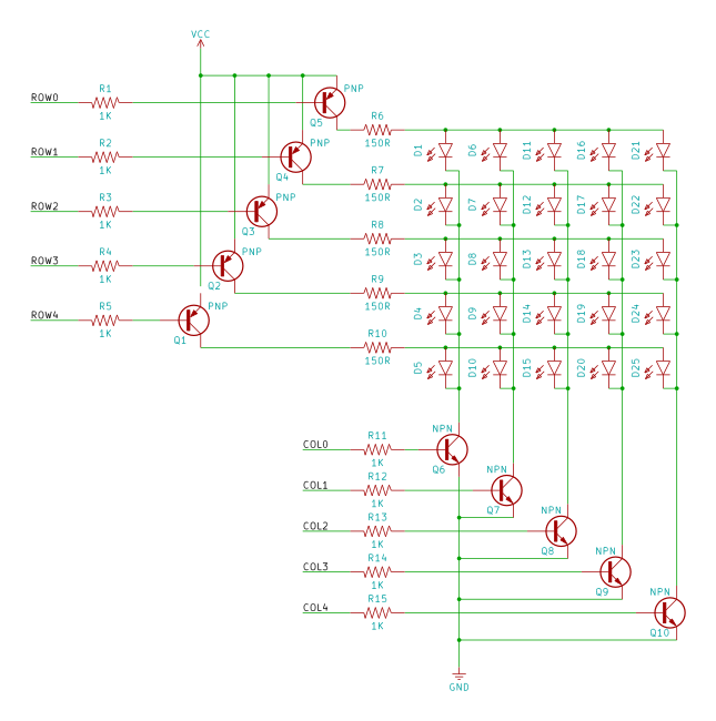
LED Matrix driver
Not much to this. The board will distribute the column and row lines to the matrix. Since the microcontroller on the LED Matrix controller can only provide a limited amount of current (less than we want to use), the driver will use some BJTs (Bipolar Junction Transistors) to provide more current for our LEDs. Because I haven’t decided on the end number of LEDs I’m going to use per each box, I made both the columns and rows controlled by transistors.
Schematic
Pictures
… Image of matrix driver …
Components
- 5 x 2N3904 BJTs - for the columns (need at least 150 mA IC - the 2N3904 can provide up to 300 mA)
- 5 x 2N3906 BJTs - for the rows (just in case I want to drive 4 LEDs per box - that will be in excess of 40 mA)
- 10 x 1K Ohm - BJT base control (column input)
- 5 x 150 Ohm (may vary) - Row LED current limiting resistor
- 2 x 0.1” 6 position screw-down terminal blocks - makes it easier for cabling
LED Matrix Controller
The LED Matrix Controller does everything that a MAX7219/MAX7221 does (keeps a 5 x 5 block of memory for the current display, and multiplexes the rows and columns).
But wait! There’s more!
Our LED Matrix controller displays a grayscale 5 x 5 display. Each “pixel” can be one of 48 shades.
It also handles “orientation” - if you want it to rotate the matrix 90 degrees, for example. Or upside-down.
Want to set pixels individually? Sure.
Components
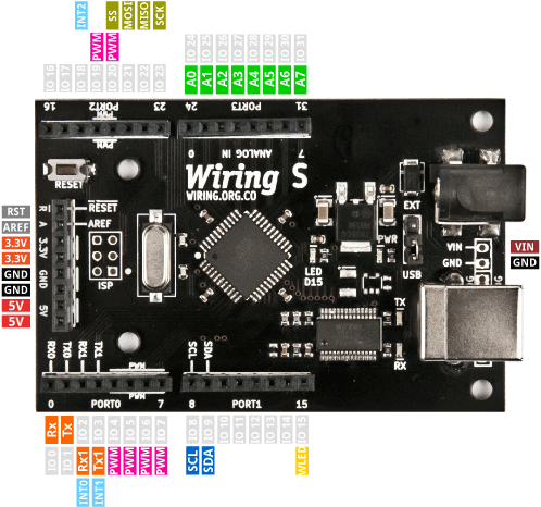
- Wiring S board (Atmel ATmega644P @ 16 MHz
Source Code
Well, there are really three pieces to the LED Matrix controller.
- Interrupt driven scan routine (dotScan5x5.pde, font5x5.c)
- Serial packet handler (very simple) (SerialMessage.pde)
- Main logic (MatrixDisplayController.pde)
Scan Routine (dotScan5x5.pde)
This is the interrupt driven routine for displaying the current display buffer on the LED matrix.
dotScan5x5.pde
/**
 * LED Matrix Support Methods
 *
 */

#include <SoftPWM.h>
#include <avr/pgmspace.h>

#define MAX_INTENSITY 48
#define DS_NORTH 0
#define DS_EAST 1
#define DS_SOUTH 2
#define DS_WEST 3

// ** Our Font
extern PROGMEM prog_uint8_t font5x5[];

// ** Variables
//uint8_t dotBuf[5];
uint8_t mBuf[5][5];
uint8_t dS_orientation = 0;

// ** Constants
// LEDHead Proto
//const uint8_t rows[] = { 14, 15, 16, 17, 18 };
//const uint8_t cols[] = { 8, 9, 10, 11, 12 };

const uint8_t rows[] = { 16, 17, 18, 19, 20 };
const uint8_t cols[] = { 24, 25, 26, 27, 28 };


void (*tasksFunction)(void);

void dS_setTasksFunction(void (*tFunc)(void))
{
  tasksFunction = tFunc;
}


void dS_tasksDelay(unsigned long ms)
{
  unsigned long start = millis();

  while ((millis() - start) < ms)
  {
    if (tasksFunction != NULL)
      tasksFunction();
  }
}


void dS_setOrientation(uint8_t o)
{
  uint8_t col, row;
  uint8_t source[5][5];

  // I'm sure there is an easier way to do this.
  // Just keeping it simple for now. Let me know if you
  // have an easier way to do this.

  // first, get our base bitmap back
  for (col = 0; col < 5; col++)
  {
    for (row = 0; row < 5; row++)
    {
      switch (dS_orientation)
      {
        case DS_NORTH:
          source[col][row] = mBuf[col][row];
          break;
        case DS_EAST:
          source[col][row] = mBuf[4-row][col];
          break;
        case DS_SOUTH:
          source[col][row] = mBuf[4-col][4-row];
          break;
        case DS_WEST:
          source[col][row] = mBuf[row][4-col];
          break;
      }
    }
  }

  dS_orientation = o;

  // now remap

  for (col = 0; col < 5; col++)
  {
    for (row = 0; row < 5; row++)
    {
      switch (dS_orientation)
      {
        case DS_NORTH:
          mBuf[col][row] = source[col][row];
          break;
        case DS_EAST:
          mBuf[4-row][col] = source[col][row];
          break;
        case DS_SOUTH:
          mBuf[4-col][4-row] = source[col][row];
          break;
        case DS_WEST:
          mBuf[row][4-col] = source[col][row];
          break;

/*
        case DS_NORTH:
          mBuf[col][row] = source[col][row];
          break;
        case DS_EAST:
          mBuf[col][row] = source[4-row][col];
          break;
        case DS_SOUTH:
          mBuf[col][row] = source[4-col][4-row];
          break;
        case DS_WEST:
          mBuf[col][row] = source[row][4-col];
          break;
*/
      }
    }
  }
}


void setPeriod(uint32_t microseconds)
{
  uint8_t clockSelect;
#define RESOLUTION 65536

  uint32_t cycles = (F_CPU/1000 * microseconds) / 1000;

  if (cycles < RESOLUTION)              clockSelect = CLOCK_NO_PRESCALE;      // no prescale, full xtal
  else if ((cycles »= 3) < RESOLUTION) clockSelect = CLOCK_PRESCALE_8;       // prescale by /8
  else if ((cycles »= 3) < RESOLUTION) clockSelect = CLOCK_PRESCALE_64;      // prescale by /64
  else if ((cycles »= 2) < RESOLUTION) clockSelect = CLOCK_PRESCALE_256;     // prescale by /256
  else if ((cycles »= 2) < RESOLUTION) clockSelect = CLOCK_PRESCALE_1024;    // prescale by /1024
  else         cycles = RESOLUTION - 1, clockSelect = CLOCK_PRESCALE_1024;    // request was out of bounds, set as maximum

  Timer1.setMode(0b0100);                                                                  // CTC mode (OCR1A = TOP)
  Timer1.setOCR(CHANNEL_A, cycles);  // must set the OCR AFTER mode
  Timer1.setClockSource(clockSelect);
}


// ** Our interrupt routine
void dotScan(void)
{
  static uint8_t currBuf[5][5];
  static uint8_t currCol = 0;
  uint8_t i, j;

  // DEBUG
//  digitalWrite(13, 1);

  // Turn off the last column
  if (currCol == 0)
    digitalWrite(cols[4], 0);
  else
    digitalWrite(cols[currCol-1], 0);

  // now turn on rows (before turning on column)

  // Binary version
  // //for (i=0; i<5; i++)
  // //  digitalWrite(rows[i], !((currBuf[currCol] » i) & 1));
  //PORTA &= 0b11100000;  // clear the port first
  //PORTA |= currBuf[currCol] & 0b00011111;

  // PWM version
//  for (i=0; i<5; i++)
//    if ((currBuf[currCol] » i) & 1)
//      SoftPWMSet(rows[i], intensity, 1);
//    else
//    {
//      SoftPWMSet(rows[i], 0, 1);
//      digitalWrite(rows[i], 0);  //set immediately
//    }

  // Grayscale PWM version
  for (i = 0; i < 5; i++)
  {
    SoftPWMSet(rows[i], currBuf[currCol][i], 1);
  }

  // turn on next column
  digitalWrite(cols[currCol], 1);

  currCol++;

  if (currCol >= 5)
  {
    // blit in the new screen
    for (i = 0; i < 5; i++)
      for (j = 0; j < 5; j++)
        currBuf[i][j] = mBuf[i][j];

    // reset to the first column
    currCol = 0;
  }

  // DEBUG
//  digitalWrite(13, 0);
}


void dS_rightToLeftChar(uint8_t ch, uint8_t intensity, int dtime)
{
  uint8_t i, j, k;
  uint8_t newcol;

  // feed in one column first

  for (i = 0; i < 4; i++)
    for (j = 0; j < 5; j++)
      mBuf[i][j] = mBuf[i+1][j];

  for (j = 0; j < 5; j++)
    mBuf[4][j] = 0;

  dS_tasksDelay(dtime);

  // now shift in each column of the char
  for (k = 0; k < 5; k++)
  {
    // shift existing
    for (i = 0; i < 4; i++)
      for (j = 0; j < 5; j++)
        mBuf[i][j] = mBuf[i+1][j];

    // now load a new column
    // dotBuf[4] = pgm_read_byte(font5x5 + ((uint8_t)(c - 32))*5 + i);
    newcol = pgm_read_byte(font5x5 + ((uint8_t)(ch - 32))*5 + k);

    for (j = 0; j < 5; j++)
    {
      if (newcol & 1)
        mBuf[4][j] = intensity;
      else
        mBuf[4][j] = 0;
      newcol »= 1;
    }

    dS_tasksDelay(dtime);
  }
}


void dS_loadChar(uint8_t ch, uint8_t intensity)
{
  // c = char
  uint8_t i, j;
  uint8_t newcol;

  if (ch >= 32 && ch <= 90)
  {
    for (i = 0; i < 5; i++)
    {
      newcol = pgm_read_byte(font5x5 + ((uint8_t)(ch - 32))*5 + i);

      for (j = 0; j < 5; j++)
      {
        if (newcol & 1)
          mBuf[i][j] = intensity;
        else
          mBuf[i][j] = 0;
        newcol »= 1;
      }
    }
  }
  else
  {
    for (i = 0; i < 5; i++)
      for (j = 0; j < 5; j++)
        mBuf[i][j] = 0;
  }
}


void dS_loadmBuf(uint8_t data, uint8_t col, uint8_t row)
{
  if (col > 4)
    col = 4;
  if (row > 4)
    row = 4;

  switch (dS_orientation)
  {
    case DS_NORTH:
      mBuf[col][row] = data;
      break;
    case DS_EAST:
      mBuf[4-row][col] = data;
      break;
    case DS_SOUTH:
      mBuf[4-col][4-row] = data;
      break;
    case DS_WEST:
      mBuf[row][4-col] = data;
      break;

/*
    case DS_NORTH:
      mBuf[col][row] = load[col][row];
      break;
    case DS_EAST:
      mBuf[col][row] = load[4-row][col];
      break;
    case DS_SOUTH:
      mBuf[col][row] = load[4-col][4-row];
      break;
    case DS_WEST:
      mBuf[col][row] = load[row][4-col];
      break;
*/
  }
}


void dS_loadmBuf(uint8_t *columnData, uint8_t col)
{
  uint8_t row;

  for (row = 0; row < 5; row++)
  {
    dS_loadmBuf(columnData[row], col, row);
  }
}

void dS_loadmBuf(uint8_t *load)
{
  // loads the mBuf, according to current orientation (NORTH = TOP)
  uint8_t col, row;

  for (col = 0; col < 5; col++)
  {
    dS_loadmBuf(&load[col * 5], col);
  }
}


void dS_changeIntensity(int8_t changeAmount)
{
  uint8_t col, row;
  int8_t newval;

  for (col = 0; col < 5; col++)
  {
    for (row = 0; row < 5; row++)
    {
      newval = mBuf[col][row];
      if (newval > 0)
      {
        newval += changeAmount;
        if (newval < 0)
          newval = 0;
        else if (newval > MAX_INTENSITY)
          newval = MAX_INTENSITY;

        mBuf[col][row] = newval;
      }
    }
  }
}


void dotScanSetup(void)
{
  uint8_t i;

  dS_orientation = DS_NORTH;
  tasksFunction = NULL;

  // For binary version
  //DDRA = 0b00011111;
  //PORTA = 0b00011111;

  SoftPWMBegin(SOFTPWM_INVERTED);
  for (i=0; i<5; i++)
    SoftPWMSet(rows[i], 0);

  for (i=0; i<5; i++)
  {
    // Needed for binary version:
    // pinMode(rows[i], OUTPUT);
    // digitalWrite(rows[i], 1);
    pinMode(cols[i], OUTPUT);
    digitalWrite(cols[i], 0);
  }

//  Timer1.initialize(3333);
  Timer1.attachInterrupt(INTERRUPT_COMPARE_MATCH_A, dotScan);
  setPeriod(3333);
}
Here is the font file for dotScan5x5.pde (a small 5x5 font - uppercase only - that I made):
font5x5.c
#include <avr/pgmspace.h>

PROGMEM prog_uint8_t font5x5[] = {
0b00000, 0b00000, 0b00000, 0b00000, 0b00000,  // 32 <sp>
0b00000, 0b00000, 0b10111, 0b00000, 0b00000,  // 33 !
0b00000, 0b00011, 0b00000, 0b00011, 0b00000,  // 34 "
0b01010, 0b11111, 0b01010, 0b11111, 0b01010,  // 35 #
0b10010, 0b10101, 0b11111, 0b10101, 0b01001,  // 36 $
0b10011, 0b01011, 0b00100, 0b11010, 0b11001,  // 37 %
0b01010, 0b10101, 0b10110, 0b01000, 0b10100,  // 38 &
0b00000, 0b00000, 0b00011, 0b00000, 0b00000,  // 39 '
0b00000, 0b00000, 0b01110, 0b10001, 0b00000,  // 40 (
0b00000, 0b10001, 0b01110, 0b00000, 0b00000,  // 41 )
0b00000, 0b01010, 0b00100, 0b01010, 0b00000,  // 42 *
0b00100, 0b00100, 0b11111, 0b00100, 0b00100,  // 43 +
0b00000, 0b10000, 0b01000, 0b00000, 0b00000,  // 44 ,
0b00100, 0b00100, 0b00100, 0b00100, 0b00100,  // 45 -
0b00000, 0b00000, 0b10000, 0b00000, 0b00000,  // 46 .
0b10000, 0b01000, 0b00100, 0b00010, 0b00001,  // 47 /
0b01110, 0b11001, 0b10101, 0b10011, 0b01110,  // 48 0
0b00000, 0b10010, 0b11111, 0b10000, 0b00000,  // 49 1
0b11001, 0b10101, 0b10101, 0b10101, 0b10010,  // 50 2
0b10001, 0b10101, 0b10101, 0b10101, 0b01010,  // 51 3
0b00011, 0b00100, 0b00100, 0b00100, 0b11111,  // 52 4
0b10111, 0b10101, 0b10101, 0b10101, 0b01001,  // 53 5
0b01110, 0b10101, 0b10101, 0b10101, 0b01001,  // 54 6
0b00001, 0b11001, 0b00101, 0b00011, 0b00001,  // 55 7
0b01010, 0b10101, 0b10101, 0b10101, 0b01010,  // 56 8
0b00010, 0b10101, 0b10101, 0b01101, 0b00110,  // 57 9
0b00000, 0b00000, 0b01010, 0b00000, 0b00000,  // 58 :
0b00000, 0b10000, 0b01010, 0b00000, 0b00000,  // 59 ;
0b00000, 0b00100, 0b01010, 0b10001, 0b00000,  // 60 <
0b00000, 0b01010, 0b01010, 0b01010, 0b00000,  // 61 =
0b00000, 0b10001, 0b01010, 0b00100, 0b00000,  // 62 >
0b00010, 0b00001, 0b10101, 0b00101, 0b00010,  // 63 ?
0b01110, 0b10001, 0b10111, 0b10101, 0b00110,  // 64 @
0b11110, 0b00101, 0b00101, 0b00101, 0b11110,  // 65 A
0b11111, 0b10101, 0b10101, 0b10101, 0b01010,  // 66 B
0b01110, 0b10001, 0b10001, 0b10001, 0b10001,  // 67 C
0b11111, 0b10001, 0b10001, 0b10001, 0b01110,  // 68 D
0b11111, 0b10101, 0b10101, 0b10101, 0b10101,  // 69 E
0b11111, 0b00101, 0b00101, 0b00001, 0b00001,  // 70 F
0b01110, 0b10001, 0b10101, 0b10101, 0b01101,  // 71 G
0b11111, 0b00100, 0b00100, 0b00100, 0b11111,  // 72 H
0b00000, 0b10001, 0b11111, 0b10001, 0b00000,  // 73 I
0b01000, 0b10000, 0b10000, 0b10000, 0b01111,  // 74 J
0b11111, 0b00100, 0b00110, 0b00101, 0b11000,  // 75 K
0b11111, 0b10000, 0b10000, 0b10000, 0b10000,  // 76 L
0b11111, 0b00010, 0b00100, 0b00010, 0b11111,  // 77 M
0b11111, 0b00010, 0b00100, 0b01000, 0b11111,  // 78 N
0b01110, 0b10001, 0b10001, 0b10001, 0b01110,  // 79 O
0b11111, 0b00101, 0b00101, 0b00101, 0b00010,  // 80 P
0b01110, 0b10001, 0b10001, 0b11110, 0b10000,  // 81 Q
0b11111, 0b00101, 0b00101, 0b01101, 0b10010,  // 82 R
0b10010, 0b10101, 0b10101, 0b10101, 0b01001,  // 83 S
0b00001, 0b00001, 0b11111, 0b00001, 0b00001,  // 84 T
0b01111, 0b10000, 0b10000, 0b10000, 0b01111,  // 85 U
0b00011, 0b01100, 0b10000, 0b01100, 0b00011,  // 86 V
0b11111, 0b01000, 0b00100, 0b01000, 0b11111,  // 87 W
0b10001, 0b01010, 0b00100, 0b01010, 0b10001,  // 88 X
0b00001, 0b00010, 0b11100, 0b00010, 0b00001,  // 89 Y
0b10001, 0b11001, 0b10101, 0b10011, 0b10001  // 90 Z
};
Serial Packet Handler (SerialMessage.pde)
This manages serial packets.
SerialMessage.pde
#define MAX_BUFFER 256

#define SOM 0xaa
#define EOM 0x55

#define ST_START      0
#define ST_GET_LENGTH 1
#define ST_GET_DATA   2
#define ST_GET_EOM    3
#define ST_COMPLETE   4
#define ST_MSG_ERROR  5

uint16_t errorCountMissedSOM = 0;
uint8_t msgBuffer[MAX_BUFFER];

uint8_t getByte(void)
{
  while (!Serial1.available());
  return Serial1.read();
}

inline void putByte(uint8_t c)
{
  Serial1.write(c);
}

int16_t getMessage(void)
{
  uint8_t msgParseState;
  uint8_t msgLength = 0;
  uint8_t i = 0;
  uint8_t c;

  msgParseState = ST_START;
  errorCountMissedSOM = 0;

  while ((msgParseState != ST_COMPLETE) && (msgParseState != ST_MSG_ERROR))
  {
    c = getByte();

    switch (msgParseState)
    {
      case ST_START:
        if (c == SOM)
          msgParseState = ST_GET_LENGTH;
        else
          errorCountMissedSOM++;
        break;

      case ST_GET_LENGTH:
        msgLength = c;
        if (c == 0)
          msgParseState = ST_GET_EOM;
        else
          msgParseState = ST_GET_DATA;
        break;

      case ST_GET_DATA:
        msgBuffer[i++] = c;
        if (i == msgLength)
          msgParseState = ST_GET_EOM;
        break;

      case ST_GET_EOM:
        if (c == EOM)
          msgParseState = ST_COMPLETE;
        else
          msgParseState = ST_MSG_ERROR;
        break;

    } // switch
  } // while (msgParseState)

  if (msgParseState == ST_COMPLETE)
    return msgLength;
  else
    return -1;
}


void putMessage(uint8_t data[], uint16_t length)
{
  uint8_t i;

  if (length > 256)
    length = 256;
  putByte(SOM);
  putByte(length);
  i = 0;
  while (i < length)
    putByte(data[i++]);
  putByte(EOM);
}
Main Logic (MatrixDisplayController.pde)
MatrixDisplayController.pde
/**
 * Rogue Robotics DLT
 * LED Matrix Controller
 * Utilizing a Wiring S board
 *
 * by Brett Hagman
 * http://roguerobotics.com/
 * http://wiring.org.co/
 *
 * This controller will handle the 5x5 display directly.  It uses a simple message protocol
 * to display text and graphics on the 5x5 display.
 *
 * SerialMessage.pde handles messages incoming/outgoing.
 * dotScan5x5.pde handles the display directly using timers.
 * font5x5.c is a simple 5x5 font.
 *
 */

extern uint8_t msgBuffer[];

void setup()
{
  dotScanSetup();
  Serial.begin(115200);
  Serial1.begin(115200);

  pinMode(13, OUTPUT);
  digitalWrite(13, LOW);
}


uint8_t toProgressBar(uint8_t barSize, double value, double inputMin, double inputMax)
{
  inputMax -= inputMin;

  value -= inputMin;

  if (value < 0)
    value = 0;

  value = (((double)barSize) * value) / inputMax;
  return (1«byte(value)) - 1;
}

uint8_t bitReverse(uint8_t in, uint8_t bitcount)
{
  uint8_t v = in;          // input bits to be reversed
  uint8_t r = v;           // r will be reversed bits of v; first get LSB of v
  int8_t s = bitcount - 1; // extra shift needed at end

  for (v »= 1; v; v »= 1)
  {
    r «= 1;
    r |= v & 1;
    s--;
  }
  r «= s; // shift when v's highest bits are zero

  return r;
}

#define NORTH 0
#define EAST 1
#define SOUTH 2
#define WEST 3

void loop()
{
  int16_t msgLength = 0;
  uint8_t col, row, val;

  // 5x5 (possibly 8x8 eventually) matrix display
  // protocol
  //
  // Serial
  // <SOM><LEN>CMD DATA<EOM>
  //
  // Commands:
  //
  // Display char - display char
  // <SOM><3> 'C' char intensity <EOM>
  //
  // Set orientation
  // <SOM><2> 'O' 'N'/'E'/'S'/'W' <EOM>
  // (i.e. Top of display is at cardinal point)
  //
  // Set display (raw)
  // <SOM><26> 'R' b1 b2 b3 b4 b5 ... b25 <EOM>
  //
  // Set column (raw)
  // <SOM><7> 'V' col b1 b2 b3 b4 b5 <EOM>
  //
  // Set pixel (raw)
  // <SOM><4> 'P' col row b1 <EOM>
  //
  // Bar (progress bar) value
  // <SOM><4> 'b' column value intensity <EOM>
  // column = 0 to 4 (left to right)
  // value = 0 to 5 - leds lit
  //
  // Bar (progress bar) percentage
  // <SOM><4> 'B' column value intensity <EOM>
  // value = 0 to 100
  //

  // Increase/decrease Intensity
  // Increase all NON-ZERO intensities by set amount (+ve/-ve)
  // -127 → +127 range (signed 8 bit value)
  // <SOM><2> 'i' value <EOM>

  // PROBABLY NOT NEEDED
  // Set intensity value
  // <SOM><2> 's' value <EOM>
  // value = 0 to 15
  //
  // Set intensity percentage
  // <SOM><2> 'S' value <EOM>
  // value = 0 to 100


  if ((msgLength = getMessage()) > 0)
  {

    // Display char - display char
    // <SOM><3> 'C' char intensity <EOM>
    if (msgBuffer[0] == 'C' && msgLength == 3)
    {
      dS_loadChar(msgBuffer[1], msgBuffer[2]);
      // Serial.println(msgBuffer[2], DEC);
    }

    // Bar (progress bar) value
    // <SOM><3> 'b' column value <EOM>
    // column = 0 to 4 (left to right)
    // value = 0 to 5 - leds lit
    else if (msgBuffer[0] == 'b' && msgLength == 4)
    {
      col = msgBuffer[1];
      row;
      val = msgBuffer[2];

      if (col >= 0 && col <= 4)
      {
        if (val > 5)
          val = 5;

        val = bitReverse((1 « val) - 1, 5);

        for (row = 0; row < 5; row++)
        {
          if (val & 1)
            dS_loadmBuf(msgBuffer[3], col, row);
          else
            dS_loadmBuf(0, col, row);
          val »= 1;
        }
      }
    }


    // Set display (raw)
    // <SOM><26> 'R' b1 b2 b3 b4 b5 ... b25 <EOM>
    else if (msgBuffer[0] == 'R' && msgLength == 26)
    {
      dS_loadmBuf(&msgBuffer[1]);
    }

    // Set column (raw)
    // <SOM><7> 'V' col b1 b2 b3 b4 b5 <EOM>
    else if (msgBuffer[0] == 'V' && msgLength == 7)
    {
      dS_loadmBuf(&msgBuffer[2], msgBuffer[1]);
    }

    // Set pixel (raw)
    // <SOM><4> 'P' col row b1 <EOM>
    else if (msgBuffer[0] == 'P' && msgLength == 4)
    {
      dS_loadmBuf(msgBuffer[3], msgBuffer[1], msgBuffer[2]);
    }

    // Increase/decrease Intensity
    // Increase all NON-ZERO intensities by set amount (+ve/-ve)
    // -127 → +127 range (signed 8 bit value)
    // <SOM><2> 'i' value <EOM>
    else if (msgBuffer[0] == 'i' && msgLength == 2)
    {
      dS_changeIntensity((int8_t) msgBuffer[1]);
    }
    // Set orientation
    // <SOM><2> 'O' 'N'/'E'/'S'/'W' <EOM>
    // (i.e. Top of display is at cardinal point)
    else if (msgBuffer[0] == 'O' && msgLength == 2)
    {
      switch (msgBuffer[1])
      {
        case 'N':
          dS_setOrientation(NORTH);
          break;
        case 'E':
          dS_setOrientation(EAST);
          break;
        case 'S':
          dS_setOrientation(SOUTH);
          break;
        case 'W':
          dS_setOrientation(WEST);
          break;
      }
    }
    else
    {
      Serial.println("Bad command");
    }
  }
  else
  {
    Serial.println("Failed message");
  }
}
Master Controller
… Info on the Master Controller …
Appendix/Notes
I use the latest 1.0 release candidate version of Wiring IDE for all firmware development. Hernando, Alexander and I are working to get the new version of Wiring out as soon as we can, so the development I do with the DLT controllers will test a lot of aspects of the new IDE.